 |
| Nasrul, Yusuf, Akmal |
Monday, 19 November 2012

RESULT FROM TESTING
Result
Early Warnng Fault Detection System is a system protection that give early alert SMS when overload happen. when the motor in overload condition, the alert SMS will send to the selected personal. The result is shown below.
The system will startup and reading the velocity of motor until the motor is in overload condition then the GSM will send notification to the selected personal.
1. The Main Board, Arduino Controller, DC speed controller and Rotary Encoder is in On condition.Motor start rotate.

2. When Overload happen, Main Board is in trip condition and DC Speed Controller will stop but Arduino Controller still On to ready send the notification.

3. Serial Monitor show the overload happen.


4. GSM send the notification to the Phone.

Early Warnng Fault Detection System is a system protection that give early alert SMS when overload happen. when the motor in overload condition, the alert SMS will send to the selected personal. The result is shown below.
The system will startup and reading the velocity of motor until the motor is in overload condition then the GSM will send notification to the selected personal.
1. The Main Board, Arduino Controller, DC speed controller and Rotary Encoder is in On condition.Motor start rotate.
2. When Overload happen, Main Board is in trip condition and DC Speed Controller will stop but Arduino Controller still On to ready send the notification.
3. Serial Monitor show the overload happen.
4. GSM send the notification to the Phone.
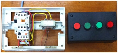
SYSTEM PROTOTYPE EARLY WARNING FAULT DETECTION SYSTEM
This system will be apply to any industry because the concept is protection and the picture below is the prototype of the system.

SYSTEM DESIGN FOR EACH PARTS
Parts of the Early Warning Fault Detection System.
1. Main Board Circuit
2. DC Speed Controller

3. Rotary Encoder Sensor

4. Arduino Controller and GSM Shield

1. Main Board Circuit
2. DC Speed Controller
3. Rotary Encoder Sensor
4. Arduino Controller and GSM Shield
PROGRAMMING EARLY WARNING FAULT DETECTION SYSTEM
Coding for Early Warning Fault Detection System.
//**************************************************************************
char number[]="+60166638494"; //Destination number
char text[]="MOTOR OVERLOAD SYSTEM TRIP PLEASE CHECKING!!! sent by GSM Arduino"; //SMS to send
byte type_sms=SMS_UNREAD; //Type of SMS
byte del_sms=0; //0: No deleting sms - 1: Deleting SMS
//**************************************************************************
Serial.begin(9600);
attachInterrupt(0, count, CHANGE);
current_time = millis();
Serial.println("system startup");
gsm.TurnOn(9600); //module power on
gsm.InitParam(PARAM_SET_1);//configure the module
gsm.Echo(0); //enable AT echo
pinMode (LED, OUTPUT);
pinMode(BUTTON, INPUT);
}
void loop ()
{
if ( millis() >= current_time + time_interval)
{
velocity = (hits*(wheel_radius * 392.7))/time_interval;//the constant is 2*pi*1000/16
Serial.println(velocity);
hits = 0;
current_time = millis();
digitalWrite(LED, HIGH);
Serial.print("Send SMS to ");
Serial.println(number);
error=gsm.SendSMS(number,text);
}
}
}
void count()
{
hits++;
}
#include <GSM_Shield.h>
# define LED 13
# define BUTTON 7
GSM gsm;
int error;
int hits = 0;
float wheel_radius = 1;
volatile unsigned int current_time;
long time_interval = 1000; //how often do you want to know velocity (milliseconds)
float velocity; //this is the velocity in length units / time_interval
# define LED 13
# define BUTTON 7
GSM gsm;
int error;
int hits = 0;
float wheel_radius = 1;
volatile unsigned int current_time;
long time_interval = 1000; //how often do you want to know velocity (milliseconds)
float velocity; //this is the velocity in length units / time_interval
//**************************************************************************
char number[]="+60166638494"; //Destination number
char text[]="MOTOR OVERLOAD SYSTEM TRIP PLEASE CHECKING!!! sent by GSM Arduino"; //SMS to send
byte type_sms=SMS_UNREAD; //Type of SMS
byte del_sms=0; //0: No deleting sms - 1: Deleting SMS
//**************************************************************************
void setup ()
{
{
Serial.begin(9600);
attachInterrupt(0, count, CHANGE);
current_time = millis();
Serial.println("system startup");
gsm.TurnOn(9600); //module power on
gsm.InitParam(PARAM_SET_1);//configure the module
gsm.Echo(0); //enable AT echo
pinMode (LED, OUTPUT);
pinMode(BUTTON, INPUT);
}
void loop ()
{
if ( millis() >= current_time + time_interval)
{
velocity = (hits*(wheel_radius * 392.7))/time_interval;//the constant is 2*pi*1000/16
Serial.println(velocity);
hits = 0;
current_time = millis();
if (velocity < 10)
{
{
digitalWrite(LED, HIGH);
Serial.print("Send SMS to ");
Serial.println(number);
error=gsm.SendSMS(number,text);
}
}
}
void count()
{
hits++;
}
PROGRAMMING GSM (EARLY WARNING FAULT DETECTION SYSTEM)
Coding for checking GSM.
#include <GSM_Shield.h>
# define LED 13
# define BUTTON 7
# define LED 13
# define BUTTON 7
//**************************************************************************
char number[]="+60166638494"; //Destination number
char text[]="testing the GSM sent by GSM Arduino"; //SMS to send
byte type_sms=SMS_UNREAD; //Type of SMS
byte del_sms=0; //0: No deleting sms - 1: Deleting SMS
//**************************************************************************
GSM gsm;
char sms_rx[122]; //Received text SMS
//int inByte=0; //Number of byte received on serial port
char number_incoming[20];
int call;
int error;
int val = 0;
void setup()
{
Serial.begin(9600);
Serial.println("system startup");
gsm.TurnOn(9600); //module power on
gsm.InitParam(PARAM_SET_1);//configure the module
gsm.Echo(0); //enable AT echo
pinMode (LED, OUTPUT);
pinMode(BUTTON, INPUT);
}
void loop()
{
char inSerial[5];
int i=0;
delay(2000);
val = digitalRead(BUTTON);
if (val == HIGH)
if (val == HIGH)
{
digitalWrite(LED, HIGH);
{
Serial.print("Send SMS to ");
Serial.println(number);
error=gsm.SendSMS(number,text);
}
}
else
{
digitalWrite(LED, LOW);
}
if (Serial.available() > 0)
{
while (Serial.available() > 0)
{
inSerial[i]=(Serial.read()); //read data
i++;
}
inSerial[i]='\0';
Check_Protocol(inSerial);
}
}
void Check_Protocol(String inStr)
{
Serial.print("Command: ");
Serial.println(inStr);
Serial.println("Check_Protocol");
// switch (inStr[0])
delay(1500);
return;
}
PROGRAMMING VELOCITY (EARLY WARNING FAULT DETECTION SYSTEM)
Coding for checking velocity.
int hits = 0;
float wheel_radius = 1;
volatile unsigned int current_time;
long time_interval = 1000; //how
often do you want to know velocity (milliseconds)
float velocity; //this is the velocity in length units
/ time_interval
void setup ()
{
Serial.begin(9600);
attachInterrupt(0, count, CHANGE);
current_time = millis();
}
void loop ()
{
if ( millis() >= current_time + time_interval)
{
velocity = (hits*(wheel_radius * 392.7))/time_interval;//the
constant is 2*pi*1000/16
Serial.println(velocity);
hits = 0;
current_time = millis();
}
}
void count()
{
hits++;
}
ROTARY ENCODER SENSOR
Rotary Encoder Sensor is using to measure the speed of the motor by using Arduino Controller

Electrical Characteristic

True table in normal operating condition


RE08A
is a rotary encoder kit has slotted disc (8 slots) and a simple
interface sensor board. Rotary encoder is a
sensor or transducer used to convert the data of rotary motion into a series of
electrical pulses which is readable by controller. The slotted disc has a 35mm
outside diameter with 8 slots that provides 16 transitions. The optical sensor is used to sense the 16
transitions of the slotted disc. With these transitions, controller is able to
recognize the rotary angle of the disc. With this concept, a rotary encoder can
be employed in a DC motor shaft for the controller to ‘know’ its current
position.
This rotary encoder kit has been design with the features of:
- Industrial grade PCB with high reliability yet professional outlook.
- Simple 3 pin interface (+5, Gnd and Sig).
- Included On board green LED as indicator.
- Direct connection to microcontroller (internal pull-up to 5V).
- Up to 1 KHz (1000 pulse/sec).
- Disc size: 35mm (outer diameter) x 3mm(inner diameter)
- Sensor board size: 12mm (height) x 35mm (length) x 15mm (width)
Electrical Characteristic
True table in normal operating condition
- Optical sensor at “A” will detect the missing slot of disc when the disc rotate, further generate pulses at signal pin.
- Header pin at “B” is input supply. User should connect 5V (+) to this pin.
- Header pin at “C” is ground of 5V supply, or in other words, the negative terminal of supply.
- Header pin at “D” is signal output of sensor board. This pin is internally pull-up to 5V, thus no extra component is needed for this sensor to be connected to controller.
- LED at “E” is an indicator. This LED will light ON if the disc does not block the optical sensor.
Subscribe to:
Comments (Atom)