PROJECT PROPOSAL
Early Warning Fault Detection System
STUDENT NAME: MUHAMMAD NASRULHAQ BIN
OMAR
ID NO.: 51210210292
INSTITUTION: BRITISH MALAYSIAN INSTITUE
SECTION: ELECTRICAL
SUPERVISOR: SIR MUHYI BIN YAAKOP
DATE: 02/02/2012
Objective
There are several objectives in order to complete
this “development and design Early Warning Fault Detection System”. The
objectives are:-
Ø To
prevent the motor from damage because overload current.
Ø To
get the measuring of RPM for the motor during the motor is on the fault
condition.
Ø To
generate report during equipment tripping via SMS by using the GSM.
In designing the prototype of development and design
Early Warning Fault Detection System, Proteus software is used to design the
layout of Printed Circuit Board.
To integrate between phones functionally with, the
simulation of Proteus software will represent the right output of simulation
result before getting the real output from hardware part.
Introduction
The demand of reliable and high quality power
electricity is widely required by industry and construction sector. The
development of information and communication technology also increased as a
large number of electrical users. Early Waning Fault Detection System is
designed for motor in industry by combining 1 major device which is Short
Message Service (SMS) by using the GSM. This device has their own function in
order to communicate each other to create one complete system in industry.
Early Warning Fault Detection System
is design and develops for motor or machine protection in industry. Development
and design Early Warning Fault Detection System is a project that used in
industrial. This project mainly used in industrial at the machine or motor.
This project are design to prevent the motor from damage because overload
current. With this system, the motor will be saving from damage. This is
because we are used magnetic contactor and overload relay. Magnetic contactor
is used to start electrical motor because it can prevent damage to the motor in
event the motor gets jammed or overload.
Overload relays are electrical switches typically employed in industrial
settings to protect electrical equipment from damage due to overheating in turn
caused by excessive current flow. In this project also miniature circuit
breaker are used for protecting and controlling the electricity supply to
respective electrical circuits. Circuit breakers protect electrical circuitry
from damage due to an over current condition, such as an overload condition or
a relatively high level short circuit or fault condition. Besides that, this
project also will generate report during equipment tripping with SMS by using
the GSM. This happen when there are overload current, the supply from machine
or motor will automatic trip and sent the report by using the GSM to the phone
with SMS. So with this, technician will be informing early.
For the project
of the Early Warning Fault Detection System is base on the speed of the motor
which is from the monitoring the motor by using speed drive (inverter) it can
make a fault. The fault happens from the different of RPM motor. When the speed
motor has been adjust the main board will process as a overload current then it
will trip directly. For this condition the speed sensor will collect data of
the RPM motor to send the controller PIC and make a data logger at the PC. The
controller will send the data to GSM to send the phone. Actually many of
factory use motor in all aspects, from that the condition of the motor will be
change depends on the load, current and others thing. This device is to improve
of the fault in the industries by checking their speed of the motor (RPM).
Actually this system are design and develop with no
risk to customer, save time, energy and easy to use. Since almost every person
have mobile phone and
carries most of the time this project
used a Short Message Services (SMS) to communicate with user quickly. With a
mobile phone, the user can read SMS massage at any time.
Methodology
Flow Chart
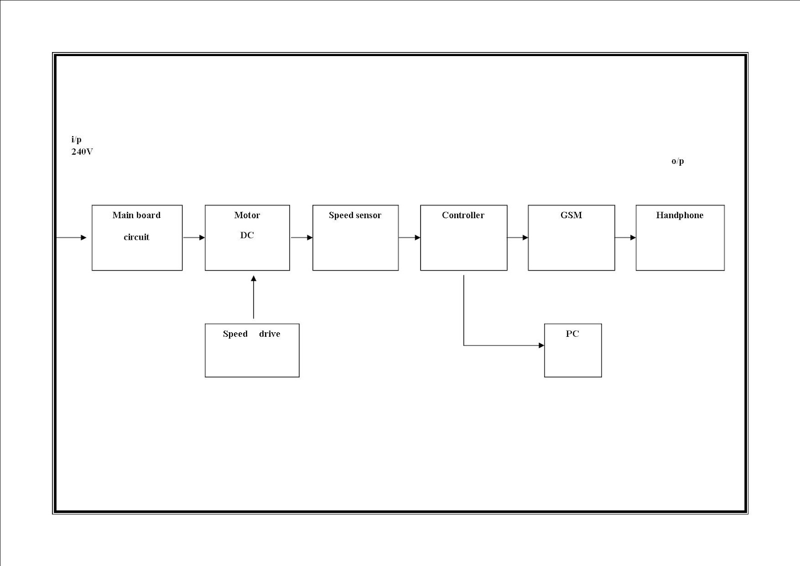
Block Diagram
Block diagram
description
Firstly is the input 240V, 240V will
supply the voltage to the main board circuit. The main board circuit will
receive the 240V to function the miniature circuit breaker (MCB), magnetic
contactor and thermal overload relay. On the main board circuit, has a
transformer to step down the voltage from 240V to 12V before the 12V supply the
motor DC. When the motor DC starts running, there is speed drive (inverter) as
a controller the speed of the motor. The inverter will make changing of the
speed motor from normal, fast, slow and stop. The inverter will make the main
board trip and make the PIC send the data. The speed of motor has record from
the speed sensor that use to read the speed motor. For the speed motor, optical
speed sensor type is more efficiency than others. From the reading of the speed
sensor it will send the data of speed to PIC (RS 232). PIC is one of the important
part to make sure the fault is happen. In the PIC, it will control the GSM and
the data logger at the PC. The data in a C language will send to the GSM that
has program to make sure the GSM can read it. GSM will program the data that
will send to the phone. The output of this Early Warning Fault Detection System
is the phone and the technician or the engineer will receive the data fault.
The data of speed motor also receive to the PC data logger. The engineer can
read all the data about the speed motor from the data logger.